1.The inverter screen is dark
Failure investigation: The inverter LCD is powered by DC; there is no DC input.
(1) Insufficient component voltage is one potential cause. The inverter’s operational voltage ranges from 100 to 500 volts; below 100 volts, it is inoperative. The module voltage and sun irradiation are connected.
(2) Reversing the PV input terminal. Positive and negative poles are present on the PV terminal; these poles should match and not be switched around with other groups.
(3) There is an open DC switch.
(4) One of the connectors is improperly attached when the parts are linked in series.
(5) All of the components stop functioning as a result of one of them being short-circuited.
Solution: Use a multimeter with a voltage class to gauge the inverter’s DC input voltage. The sum of the voltages in each group makes up the overall voltage when the voltage is normal. If there is no voltage, check each component, terminal, cable connector, and DC switch to make sure they are all in working order. If the component has many connections, each one should be evaluated independently.
Please get in touch with the company’s after-sales department if the inverter is utilised for a while and no cause is discovered.
2. An inverter that is not wired into the grid
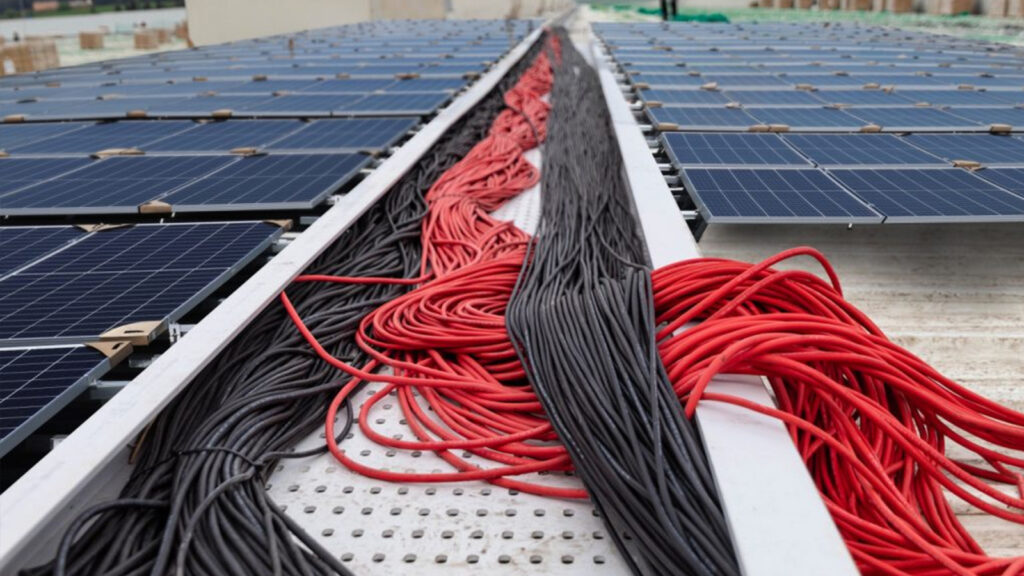
Defect analysis: The grid and the inverter are not interconnected.
Potential reasons:
(1) There is an open AC switch.
(2) There is no connection to the inverter’s AC output port.
(3) The connection line’s upper row of inverter output terminals is loose.
Solution: To determine the inverter AC output voltage, use a multimeter voltage file. Under normal conditions, the output terminals should have 220V or 380V voltage. If not, check each terminal individually to see if it is loose, whether the AC switch is closed, and whether the leakage protection switch is disconnected.
3. excessive PV voltage
Failure analysis: Alarm for excessive DC voltage.
Possible reason: There are too many components connected in series, which causes the voltage to be higher than the inverter’s operating voltage.
Solution: The lower the temperature, the higher the voltage because of how components react to temperature. The input voltage range of a three-phase string inverter is 250-800V, indicating that the voltage after the string is between 600 and 650V, and the input voltage range of a single-phase string inverter is 100-500V. The inverter is more effective in this voltage range and can produce power in the morning and evening when the irradiance is low, without the voltage surpassing the inverter’s upper limit and setting off an alarm and shutdown.
4. the isolation fault
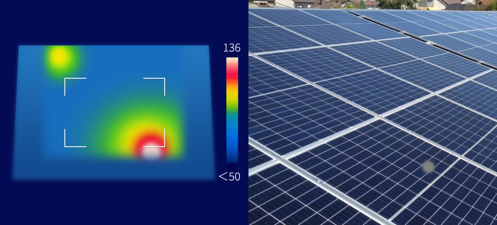
PV system insulation resistance to ground is less than 2 megohms, according to the fault analysis.
Possible causes include damaged insulation layers or wires to ground short circuits in solar modules, junction boxes, DC cables, inverters, AC cables, terminals, and other locations. Water entry was caused by loose PV terminals and AC wires.
Solution: Disconnect the grid and inverter, inspect each component’s cables individually for resistance to ground, identify the source of the issue, and replace.
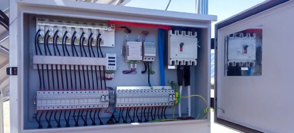
5. Current leakage fault
Failure analysis: There is too much leakage current.
Remove the PV array input, then examine the nearby AC grid. Disconnect both DC and AC terminals, allow the inverter to go into automatic recovery mode for at least 30 minutes, and then restart it if necessary. If it doesn’t, call an after-sales technical engineer.
6. isolation fault
The grid voltage and frequency are either too low or too high, according to the sixth grid error fault study.
Use a multimeter to test the voltage and frequency of the grid; if it is higher than normal, wait for the grid to return to normal. If the grid is functioning normally, the inverter detection circuit board power generation defect is the cause. Disconnect all the DC and AC terminals, wait for the inverter to lose power for at least 30 minutes, and then see if you can restart it on your own. If not, get in touch with the after-sales technical engineer.
7. Hardware inverter failure
Failure analysis: There are problems with the inverter circuit board, the power circuit, the communication circuit, and other circuits.
Solution: If the inverter is defective, please disconnect the DC and AC terminals and allow the inverter to shut off for more than 30 minutes. If you can restart the inverter on your own, use it as usual; if not, get in touch with the after-sales technical engineer.
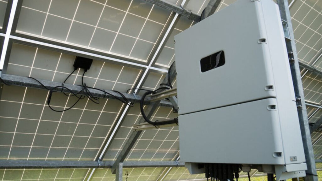
8. the system’s output power falls short of optimal levels.
Potential reasons:
The amount of solar radiation, the tilt angle of the solar cell module, dust and shadow blocking, and component temperature characteristics are only a few of the many variables that affect the output power of photovoltaic power plants.
The system power is low due to incorrect installation and configuration; typical fixes include:
(1) Before installation, check each module’s power to ensure it is adequate.
(2) Modify the modules’ position and mounting angle.
(3) Inspect the modules for dust and shadows.
(4) When connecting the modules in series, make sure the voltage is within the range; a low voltage will lower the system’s efficiency.
(5) inspect the open circuit voltage of each string before connecting numerous strings; the difference between the voltages should not be greater than 5V. If the voltage is discovered to be incorrect, inspect the wiring and connectors.
(6) The installation can be visited in batches, with each group of access being able to record the power of each group and a maximum power differential of 2% between strings.
(7) The inverter’s temperature is too high because the installation area is poorly ventilated, the inverter’s heat does not dissipate quickly enough, or it is directly exposed to sunlight.
(8) The inverter has two MPPT access points, but only one of them receives a full 50% of the entire power input. The output power will be half if just one way’s MPPT terminal is connected, even if the designed installed power of each way should theoretically be equal.
(9) Poor cable junction contact, excessively long and narrow cable diameter, and power loss are the results.
(10) The grid-connected AC switch capacity of a PV plant is insufficient to meet the demands of the inverter output.
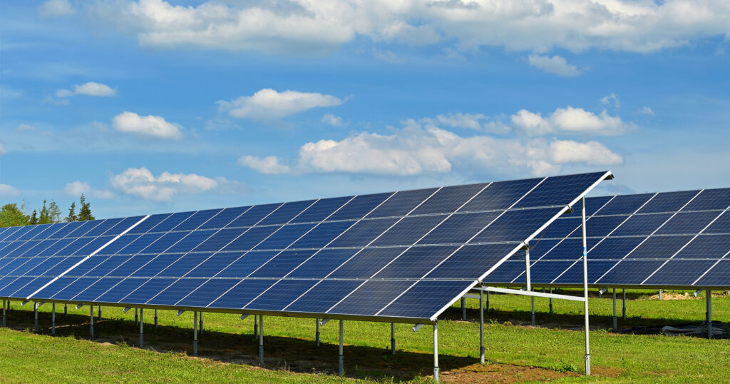
9. AC side over-voltage
Potential reasons:
Grid impedance is too high, solar power generation from the user side cannot be processed, and transmission out due to transmission out impedance is too high, resulting in the inverter output side voltage being too high, resulting in the inverter protection shutdown or derate operation.
Common fixes include:
(1) Increasing the output cable; thicker cables have lower impedance.
(2) The cable’s impedance decreases with length.
Maysun Solar, as a PV module manufacturer with 15 years of professional experience, can provide you with high quality solar panels, click the button below to contact us for a product quote.

Will Agrivoltaics Affect Crop Growth?
Agrivoltaics combines solar energy and agriculture to reduce up to 700 tons of CO₂ per MW, improve water use, and boost crop growth for sustainable farming.

6.5 Billion Loss Hits Photovoltaics: Reshaping or Elimination?
In 2025, the photovoltaic market may see a turnaround as some companies take early action. A €6.5 billion loss is driving businesses to explore new growth areas like energy storage and hydrogen. Which giants will break through? Industry transformation is accelerating!

What’s New in Solar Energy (March 2025)
March’s solar news highlights include rooftop solar meeting two-thirds of global demand, China’s market reforms potentially boosting solar demand and module prices, France revising solar targets in PPE 3, and challenges in Europe with declining capture rates and price volatility.
Zero-Investment Solar Projects: How to Earn Passive Income Through Rooftop Leasing?
Monetize your idle rooftop and earn stable annual rent! With the photovoltaic rooftop leasing model, businesses can generate long-term revenue without investment, reduce operating costs, and achieve a green transition.

How to Optimize Photovoltaic Power Plant Operations with AI and Big Data
This article explores three methods of using AI to enhance power generation revenue and reduce operation and maintenance costs in intelligent photovoltaic operations.

Solar Module Costs May Rise by 10% in 2026! In-Depth Analysis of CBAM’s Impact on the Industry
Table of Contents Introduction to CBAM 1. Why Did the EU Introduce CBAM? As the challenges posed by global climate change intensify, governments worldwide are accelerating their efforts to achieve carbon neutrality. The European Union, a leader in global carbon reduction initiatives, introduced

